Proper carrier air conditioner electrical wiring ensures safe, reliable cooling and prevents costly damage. Whether installing a new unit or fixing an old one, understanding the wiring system is essential for performance and safety. This guide walks you through everything from basic components to advanced troubleshooting.
Key Takeaways
- Understanding carrier air conditioner electrical wiring: Provides essential knowledge
Quick Answers to Common Questions
What wire size should I use for my Carrier air conditioner?
It depends on amperage and distance. For a 20-amp circuit, use 12 AWG wire. For 30 amps under 50 feet, 10 AWG is standard. Always refer to local electrical codes and your unit’s specifications.
Can I install a smart thermostat without a C-wire?
Yes, but it may require a power adapter or virtual grounding. Some smart thermostats use battery backup. However, hardwiring a C-wire ensures stable performance and eliminates battery dependency.
Why does my Carrier AC keep tripping the breaker?
Common causes include undersized wire, short circuits, or overloaded circuits. Inspect wiring for damage, verify wire gauge matches breaker rating, and ensure no other high-draw devices share the same circuit.
How do I test a capacitor in my Carrier unit?
Disconnect power and discharge the capacitor by shorting its terminals with an insulated screwdriver. Use a multimeter in capacitance mode to check if it reads within ±10% of its rated value. Replace if out of spec.
Is it safe to replace a contactor myself?
Only if you’re experienced with electrical work. Contactors handle high current and require careful handling. Always turn off power, verify no voltage, and ensure proper alignment before reconnecting. When unsure, call a pro.
📑 Table of Contents
- Understanding Carrier Air Conditioner Electrical Wiring
- The Core Components of Carrier AC Electrical Systems
- Common Wiring Configurations in Carrier Air Conditioners
- Step-by-Step Guide to Wiring a Carrier Air Conditioner
- Common Electrical Issues and How to Fix Them
- Safety Tips for Working With Carrier AC Electrical Systems
- When to Call a Professional
- Conclusion: Master Your Carrier AC’s Electrical System
Understanding Carrier Air Conditioner Electrical Wiring
If you’ve ever looked inside a Carrier air conditioning unit, you might have noticed a tangled web of wires, capacitors, and relays. While it may look complicated, understanding the basics of Carrier air conditioner electrical wiring can help you troubleshoot minor issues, perform routine maintenance, or even assist a professional during installation. This comprehensive guide breaks down the essentials in simple terms so you can feel confident about your AC’s electrical system.
Carrier has been a trusted name in HVAC systems for decades, known for reliability and innovation. Their air conditioners are engineered with precision, but like all complex machinery, they rely on proper electrical connections to function safely and efficiently. From the thermostat signals to the compressor activation, every wire plays a vital role. In this article, we’ll walk through the key components, explain common wiring configurations, and offer practical tips to keep your system running smoothly.
The Core Components of Carrier AC Electrical Systems
Before diving into wiring specifics, it’s important to understand the main electrical parts that make your Carrier air conditioner work. These components work together to convert electrical energy into cooling power. Here’s what you need to know:
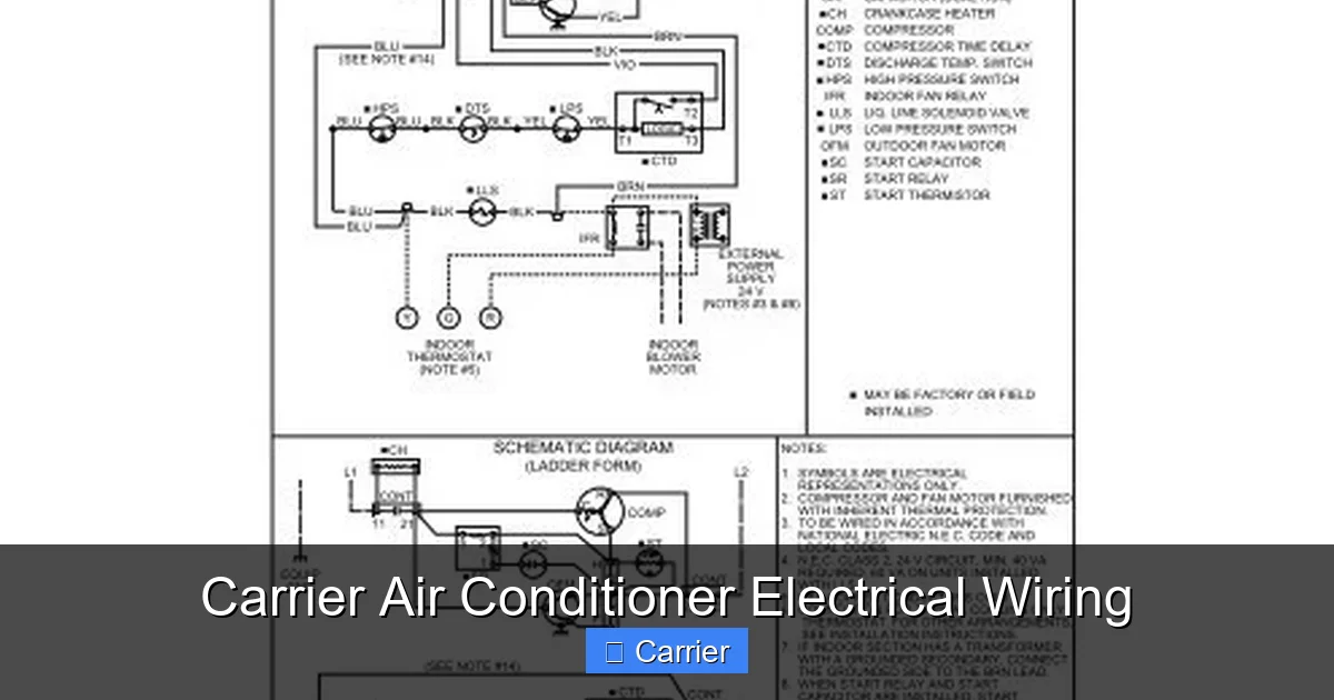
Visual guide about Carrier Air Conditioner Electrical Wiring
Image source: img.yumpu.com
The Thermostat
The thermostat is the brain of your system. It sends low-voltage signals to the control board when it detects your home needs cooling. Most modern Carrier units use a 24-volt system for signaling, which keeps wiring simpler and safer than higher-voltage systems.
The Control Board (or Logic Board)
This is where the magic happens. The control board receives signals from the thermostat and decides which components to activate—like the blower motor, compressor, and condenser fan. It also monitors sensors and protects the system from overloads.
The Compressor
The heart of the cooling process, the compressor pressurizes refrigerant to transfer heat outside. It requires high current and is typically controlled by contactors and relays managed by the control board.
The Capacitor
Capacitors store and release electrical energy to help motors start and run efficiently. In Carrier units, there are usually two: one for the compressor (start/run capacitor) and another for the condenser fan (fan capacitor).
Contactors and Relays
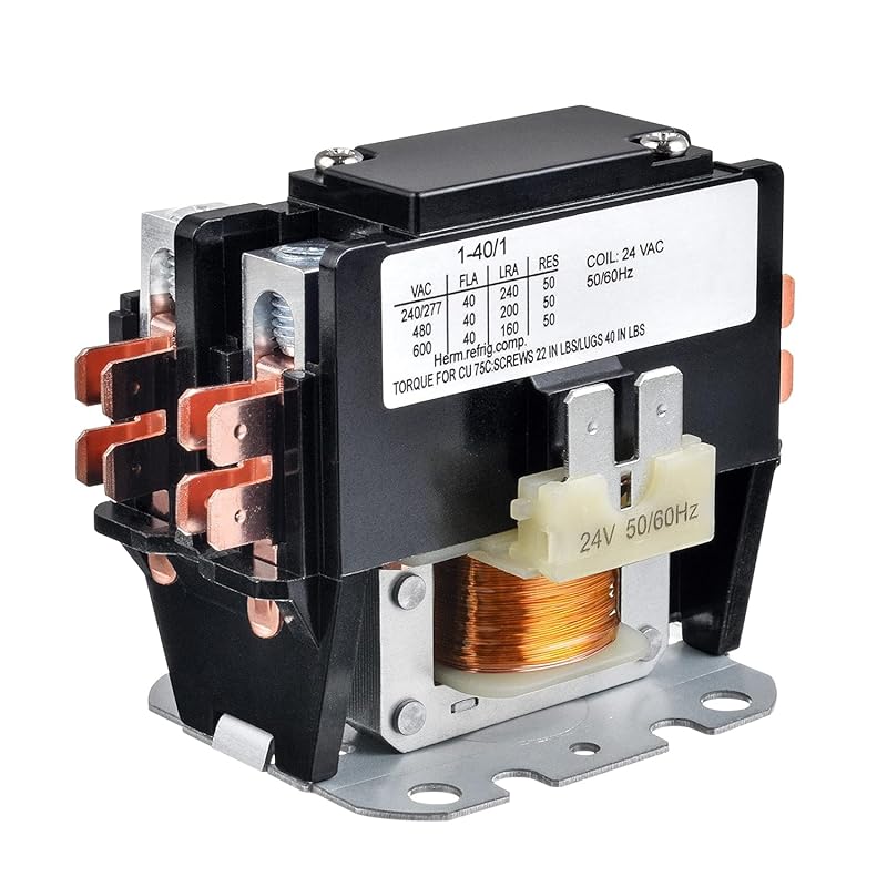
These are like electrical switches that carry high current to the compressor and fan motors. They’re activated by the control board and protect the system from surges.
Blower Motor and Indoor Fan
This circulates cool air throughout your home. Its motor is often controlled separately and may have its own capacitor or relay depending on the model.
Each of these components relies on precise wiring to communicate and operate. Miswiring can lead to poor performance, frequent cycling, or even permanent damage.
Common Wiring Configurations in Carrier Air Conditioners
Carrier offers various models—from window units to central air systems—but most share similar electrical layouts. Understanding these common configurations helps with installation and troubleshooting.

Visual guide about Carrier Air Conditioner Electrical Wiring
Image source: i1.wp.com
Single-Phase Residential Wiring
Most residential Carrier air conditioners use single-phase 240/120 volt power. This means two hot wires (L1 and L2) and one neutral (N), with one of the hots tied to ground for 120V circuits (like lights and outlets). The compressor and condenser fan usually run on 240V, while the indoor blower and controls use 120V.
Example: A typical Carrier rooftop unit might draw 30 amps. In this case, you’d use 10-gauge wire for runs under 50 feet. Longer distances may require 8-gauge to minimize voltage drop.
Three-Phase Commercial Systems
Larger commercial Carrier units often use three-phase power (208/240V or 480V). These systems have three hot legs instead of two, allowing more balanced loads and smoother motor operation. Wiring here involves six conductors (three hots, three neutrals) and grounding.
Heat Pump Configurations
Some Carrier models include heating via reversing valves. These “heat pump” systems reverse refrigerant flow to provide warmth in cold weather. The wiring adds complexity because the same outdoor unit must switch between modes, often requiring additional wires to signal the defrost cycle.
Smart Thermostat Integration
Modern Carrier systems support smart thermostats like Nest or Ecobee. These add communication wires (like C-wire for continuous power) to enable features such as remote access and energy reporting. Without a C-wire, some smart thermostats use battery backup or virtual grounding.
Always check your specific model’s wiring diagram—it’s your best reference!
Step-by-Step Guide to Wiring a Carrier Air Conditioner
While we strongly recommend hiring a licensed HVAC technician for major installations, understanding the process can empower you during maintenance or upgrades. Follow these steps carefully and prioritize safety.
Gather Tools and Materials
- Wire strippers
- Screwdrivers (Phillips and flathead)
- Voltmeter or multimeter
- Wire nuts or crimp connectors
- Electrical tape
- Correct gauge wire (check local code and manufacturer specs)
Turn Off Power Supply
Locate your main breaker panel and turn off the circuit dedicated to the AC unit. Use a non-contact voltage tester to confirm no power is flowing before touching any wires.
Identify Terminal Labels
On both the outdoor unit and indoor blower, label terminals clearly. Common labels include:
– L1, L2: Line power inputs
– N: Neutral
– G: Ground
– Y: Compressor/Yellow (cooling mode)
– O/B: Reversing valve (heat pump)
– G: Blower fan
– W: Heat strip (if applicable)
– R: Power to control board
Connect Main Power Wires
Run appropriately sized wires from your breaker to the disconnect switch near the outdoor unit. Connect L1 and L2 to the line input terminals and tie the neutral to N. Ground the unit to your grounding system.
Wire the Thermostat
Run low-voltage wires from the thermostat back to the furnace or air handler (for central systems). Typical colors are:
– Red (R): Power
– White (W): Heat
– Yellow (Y): Cooling
– Green (G): Fan
– Blue (C): Common return
Attach Capacitors Correctly
Match capacitor leads to the correct motor terminals:
– Compressor capacitor: C (common), S (start), R (run)
– Fan capacitor: FAN and COMMON
Miswiring can destroy the capacitor or motor.
Double-Check Connections
Ensure no exposed copper shows beyond wire nuts. Secure all connections and tuck wires neatly into conduits. Restore power and test the system with the thermostat set to cool.
Pro Tip: Label each wire at both ends to avoid confusion later. Use color-coded tags or zip ties.
Common Electrical Issues and How to Fix Them
Even with proper wiring, problems can arise. Many electrical issues stem from loose connections, worn-out capacitors, or outdated wiring. Here’s how to diagnose and resolve them.
Unit Doesn’t Start
Possible causes:
– Tripped breaker or blown fuse
– Faulty thermostat signal
– Open contactor coil
– Failed capacitor
Diagnosis: Check breaker first. Then test thermostat continuity. If that’s fine, measure voltage at the outdoor unit. No voltage? Trace back to disconnect. If voltage is present but the compressor won’t engage, suspect a bad capacitor or contactor.
Blower Runs Continuously or Not at All
This usually points to a wiring error in the indoor section. Verify the G terminal is connected to the fan wire. Also check for loose connections at the blower motor or control board.
Compressor Clicks But Doesn’t Run
A classic sign of a failing start capacitor. Swap it with a known-good unit if possible. Never bypass a capacitor—it’s designed to protect the motor.
Breaker Trips Frequently
Could indicate:
– Undersized wire causing overheating
– Short circuit in wiring
– Overloaded circuit
Check wire gauge against amperage rating. For example, a 20-amp circuit requires at least 12 AWG. Also inspect for frayed wires or animal damage.
Erratic Cycling or Short Cycles
Often caused by dirty coils, low refrigerant, or a faulty control board. But wiring issues—like reversed polarity or poor grounding—can mimic these symptoms.
In all cases, use a multimeter to test continuity and voltage. Document readings to help a technician pinpoint the issue faster.
Safety Tips for Working With Carrier AC Electrical Systems
Electrical work carries risks, especially around high-current components like compressors. Follow these safety practices religiously:
- Always de-energize: Turn off and lock out the breaker before handling wires.
- Use PPE: Wear insulated gloves and safety glasses.
- Verify zero energy: Test wires with a voltmeter before touching.
- Follow local codes: NEC (National Electric Code) requirements vary by region.
- Don’t overload circuits: Avoid daisy-chaining multiple devices.
- Label everything: Clear labeling prevents errors during future service.
If you’re uncomfortable with any step—especially involving 240V lines—call a pro. It’s not worth the risk.
When to Call a Professional
While DIY knowledge is valuable, certain tasks demand expert hands. Consider hiring a licensed HVAC technician when:
- You’re installing a new central AC system
- Running long wire runs across attics or crawl spaces
- Dealing with refrigerant lines (electrical and chemical hazards)
- Upgrading to a larger capacity unit that changes load requirements
- Your breaker panel is outdated or lacks proper grounding
Technicians have specialized tools like amp probes and infrared cameras to detect hidden faults. Plus, they ensure your work passes inspection and maintains warranty coverage.
Conclusion: Master Your Carrier AC’s Electrical System
Understanding Carrier air conditioner electrical wiring doesn’t require becoming an electrician overnight. By learning the core components, recognizing common configurations, and following safety protocols, you gain valuable insight into your cooling system’s inner workings. Whether you’re diagnosing a glitch, upgrading a thermostat, or simply wanting peace of mind, this knowledge empowers you to maintain your home’s comfort efficiently and safely.
Remember: when in doubt, consult the manual or a professional. Carrier provides detailed wiring diagrams for every model—take advantage of them. And never underestimate the importance of regular maintenance. Clean filters, tight connections, and updated controls go a long way toward extending your unit’s life and saving on energy bills.
With the right information and cautious approach, you can confidently handle many aspects of your Carrier AC’s electrical system—keeping your home cool and your mind at ease.
Frequently Asked Questions
Where can I find the wiring diagram for my Carrier air conditioner?
Wiring diagrams are available in your owner’s manual or downloadable from Carrier’s official website using your model number. They show exact terminal connections and color codes.
Can I use extension cords for my Carrier AC?
No. Extension cords are unsafe for permanently installed appliances like air conditioners. They can overheat and violate electrical codes. Always connect directly to a dedicated circuit.
What does the “Y” wire do in Carrier AC wiring?
The “Y” wire (yellow) signals the compressor to start cooling. It connects the thermostat to the outdoor unit and activates the refrigerant cycle when cooling is needed.
How often should I check my AC’s electrical connections?
Inspect connections annually during spring maintenance. Look for loose screws, corrosion, or burnt marks. Tighten any wobbly terminals and clean contacts gently with a dry cloth.
Will rewiring fix a noisy compressor?
Not always. Noise could stem from mechanical wear, dirty coils, or refrigerant issues. But poor wiring (like a failing capacitor) can cause erratic operation that sounds like knocking. Diagnose thoroughly before replacing parts.
Do I need a separate ground wire for my Carrier AC?
Yes. Every metal part of the unit must be grounded to prevent shock. Connect the green or bare copper wire to your home’s grounding system at the breaker panel and the unit’s ground terminal.