Understanding the wiring diagram for Carrier central air conditioners is essential for safe installation, repair, and maintenance. These diagrams show how electrical components like the thermostat, compressor, and fan are connected. Whether you’re a homeowner or technician, knowing your wiring setup helps prevent errors and ensures reliable cooling.
Key Takeaways
- Wiring diagrams are vital: They provide a clear map of how each wire connects to components in your Carrier AC unit.
- Safety first: Always turn off power before working on any part of the system to avoid electric shock.
- Model-specific differences: Carrier offers many models, so always use the correct wiring diagram for your exact unit.
- Common wire colors: Understanding color codes (like red for compressor) makes troubleshooting easier.
- Professional help recommended: If unsure, consult an HVAC technician—improper wiring can damage your system.
- Thermostat compatibility: Not all thermostats work with every Carrier model; check wiring compatibility before installation.
- Digital vs. analog systems: Newer Carrier units may use digital controls requiring updated wiring techniques.
📑 Table of Contents
- Introduction: Why Wiring Diagrams Matter for Your Carrier Central Air Conditioner
- What Is a Wiring Diagram and Why Does It Matter?
- How to Read a Carrier Central Air Conditioner Wiring Diagram
- Common Wire Colors and Their Functions
- Troubleshooting Tips Using the Wiring Diagram
- Upgrading to Smart Technology: Compatibility Considerations
- Where to Find Official Carrier Wiring Diagrams
- Final Thoughts: Safety, Accuracy, and Peace of Mind
Introduction: Why Wiring Diagrams Matter for Your Carrier Central Air Conditioner
When it comes to keeping your home cool and comfortable, few things matter more than your central air conditioning system—and few things can cause more confusion during installation or repairs than understanding the wiring diagram for Carrier central air conditioners. Carrier has long been a leader in HVAC technology, offering reliable, energy-efficient cooling solutions for homes across North America. But behind every smooth-running AC unit lies a complex network of wires connecting the thermostat, condenser, evaporator coil, blower motor, and other critical components.
A wiring diagram for Carrier central air conditioner isn’t just a technical drawing—it’s your roadmap to how electricity flows through your system. Without it, even simple tasks like replacing a thermostat or diagnosing a tripped breaker become guesswork. Whether you’re installing a new Carrier heat pump, upgrading your thermostat, or troubleshooting why your indoor unit isn’t blowing cold air, this guide will walk you through everything you need to know about interpreting and using these vital schematics.
In this comprehensive article, we’ll break down what a wiring diagram is, explain how to read one specific to Carrier models, highlight common wire functions and colors, and offer practical tips for both DIY enthusiasts and professional technicians. By the end, you’ll feel confident navigating the electrical side of your Carrier central air system—safely and effectively.
What Is a Wiring Diagram and Why Does It Matter?

Visual guide about Wiring Diagram for Carrier Central Air Conditioner
Image source: m.media-amazon.com
At its core, a wiring diagram is a simplified visual representation of how electrical circuits work within your air conditioning system. For Carrier central air conditioners, these diagrams show the connections between the outdoor condenser unit, indoor air handler, thermostat, and sometimes auxiliary components like humidifiers or dehumidifiers. Think of it as a blueprint—but instead of showing pipes and ducts, it shows wires and terminals.
These diagrams are published by Carrier and included in the installation manuals that come with new units. They’re also available online through official Carrier support portals or third-party HVAC resource sites. Each diagram corresponds to a specific model number, so using the wrong one could lead to serious problems—or worse, safety hazards.
For homeowners, having access to the right wiring diagram means you won’t have to rely solely on trial-and-error when something goes wrong. And for contractors or DIYers attempting their first AC install, following the diagram step-by-step reduces the risk of miswiring, which can fry motors, blow fuses, or void warranties.
The Role of the Thermostat in the Circuit
One of the most important parts of any Carrier central air conditioner wiring diagram is the connection point at the thermostat. This device acts as the “brain” of your system—sensing temperature changes and sending signals to activate the compressor, fan, and other components. In most systems, the thermostat connects via low-voltage wires (typically 18–24 gauge), even though the actual power delivered to the outdoor unit runs on high voltage (usually 208/230V).
The typical thermostat terminal labels include:
– **R** or **Rh**: Power source (often labeled “common” or “heat”)
– **Y**: Compressor relay (triggers cooling)
– **G**: Fan control
– **W**: Heating (if it’s a heat pump or dual-fuel system)
– **C**: Common return (for powering the thermostat itself)
On newer smart thermostats compatible with Carrier systems, you might see additional labels like **O/B**, **E**, or **Y2**. These indicate different refrigerant cycles or auxiliary heating sources. Always refer to your specific thermostat manual alongside the Carrier wiring diagram.
Components Connected in the Wiring Diagram
Let’s take a closer look at the major components you’ll find referenced in a Carrier central air conditioner wiring diagram:
– **Outdoor Unit (Condenser):** Houses the compressor, fan motor, and reversing valve (in heat pumps). The wiring diagram shows how these connect to the main power supply and to the indoor unit via the line set.
– **Indoor Unit (Air Handler or Furnace):** Contains the blower motor, evaporator coil, and sometimes a furnace for supplemental heat. Its wiring ties into the thermostat and receives power from the same circuit.
– **Compressor:** The heart of the cooling process; draws refrigerant and pressurizes it.
– **Fan Motor:** Cools the condenser coils outdoors and circulates air indoors.
– **Reversing Valve:** Found only in heat pumps; switches between heating and cooling modes.
– **Capacitor:** Stores electrical energy to help start motors efficiently.
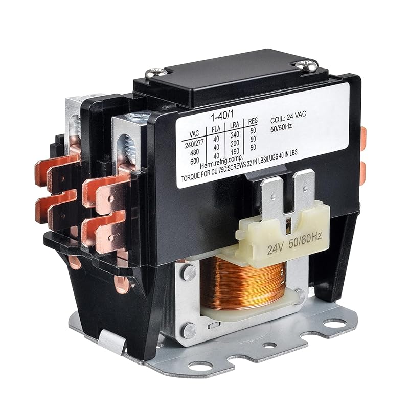
– **Contactor Relay:** A switch that controls high-power circuits using low-power signals from the thermostat.
Each of these components has specific wire assignments shown clearly on the diagram. Color-coding helps distinguish between similar functions—though always double-check against your model’s manual since variations exist between regional versions.
How to Read a Carrier Central Air Conditioner Wiring Diagram

Visual guide about Wiring Diagram for Carrier Central Air Conditioner
Image source: cdn.walkerland.com.tw
Reading a wiring diagram may seem intimidating at first glance—especially if you’re not used to electrical symbols—but once you learn the basics, it becomes second nature. Here’s how to decode one effectively:
Step 1: Identify Your Model Number
Before looking up any diagram, locate your Carrier unit’s model number. You’ll usually find it on a metal plate inside the indoor air handler or on the side of the outdoor condenser. It typically starts with “24” or “25” followed by a series of letters and numbers (e.g., 24ABA6017001). Entering this into Carrier’s official service portal will pull up the exact wiring diagram you need.
Step 2: Understand Basic Symbols
Most wiring diagrams use standardized symbols recognized across the HVAC industry:
– A circle with an “S” inside = capacitor
– Two parallel lines = resistor or contactor
– Zigzag line = heating element
– Rectangle with diagonal arrow = motor
– Letters like R, Y, G, W = thermostat terminals
Carrier diagrams often include both pictorial representations and line drawings. Pay attention to whether the diagram shows connections at the thermostat, air handler, or outdoor unit—they may differ slightly.
Step 3: Trace the Low-Voltage Circuit
Start at the thermostat and follow the colored wires back to their destinations. Most residential systems use six wires, though some advanced setups require eight or more. Common combinations include:
– Red (R) → Rh/Rc power
– Yellow (Y) → Compressor
– Green (G) → Blower fan
– White (W) → Heat (or W2 for second-stage heat)
– Blue (B) → O/B terminal (for heat pump operation)
– Orange (O) → Reversing valve (heat pump only)
– Gray (E) → Emergency heat (some heat pumps)
Note: Wire colors can vary by region and installer preference. Never assume a green wire always means “fan”—always cross-reference with your diagram.
Step 4: Check for Optional Components
Not all Carrier systems include every possible feature. Some may omit a humidifier connector, dehumidifier output, or auxiliary heat strip. If your diagram shows extra terminals labeled “HUM,” “DRY,” or “AUX,” they’re likely unused unless you’ve installed those add-ons.
Practical Example: Installing a New Thermostat
Suppose you’re swapping out an old thermostat for a Nest Learning Thermostat compatible with Carrier systems. First, turn off power at the breaker. Then remove the old wires from the base plate. Next, match each wire to its corresponding terminal on the Nest (usually color-coded). Finally, reattach the wires to the correct terminals on the Nest and snap the faceplate back on. Throughout this process, your Carrier wiring diagram confirms which terminal does what—preventing you from accidentally connecting Y (cooling) to W (heating).
Common Wire Colors and Their Functions
While wire colors aren’t strictly universal, Carrier tends to follow industry conventions consistently. Below is a general guide—but again, always verify with your specific model’s diagram.
Red (R / Rh / Rc)
This is your primary power feed. Rh (R-heat) powers the system when heating is called, while Rc (R-cool) is used in split systems where the transformer is located in the outdoor unit. In single-transformer setups, Rh and Rc are combined.
Yellow (Y)
Controls the compressor and outdoor fan. When the thermostat calls for cooling, the Y signal tells the contactor to engage the compressor.
Green (G)
Activates the indoor blower fan. Even without cooling or heating, turning on G will make the air handler run—useful for ventilation or filter cleaning.
White (W)
Triggers the heating function. In standard air conditioners (not heat pumps), W is often unused. But in dual-fuel or heat pump systems, W energizes the electric heat strips or reverses the refrigerant flow.
Blue (B)
Used in heat pump configurations to reverse refrigerant direction. Often paired with the O terminal.
Orange (O)
Same as B—controls the reversing valve. Some older systems use B instead of O.
Gray (E)
Emergency heat input. Rarely used unless you have a dedicated emergency heat source.
Purple (P), Black (K), Brown (N), etc.
These are less common and usually reserved for specialized accessories like zone dampers, UV lights, or external sensors.
Troubleshooting Tips Using the Wiring Diagram
When your Carrier central air conditioner stops working, the first place many people look is the thermostat settings—but electrical issues are often the real culprit. Here’s how to leverage your wiring diagram during diagnosis:
Check for Loose or Disconnected Wires
Over time, vibration can loosen connections at the thermostat or air handler. Use your diagram to identify where each wire should attach, then gently tug-test them to ensure they’re secure.
Test Continuity with a Multimeter
If you suspect a broken wire or faulty relay, set your multimeter to continuity mode and test between two points described in the diagram. No beep? That’s a break in the circuit.
Look for Burn Marks or Corrosion
Inspect wire insulation near terminals for signs of melting or blackening—this indicates overheating and possibly a short circuit.
Verify Correct Voltage Delivery
Using a voltmeter, confirm that the correct voltage reaches each component. For example, if the compressor isn’t starting but the thermostat shows cooling demand, check whether Y is receiving power at the contactor coil.
Don’t Ignore the Contactor Relay
The contactor is a magnetic switch that routes high voltage to the compressor and fan. If it’s clicking but the compressor won’t spin, the issue might be a bad capacitor or seized motor—but if there’s no click at all, the problem could be a failed contactor or a broken Y-wire.
Upgrading to Smart Technology: Compatibility Considerations
Today’s Carrier central air conditioners are designed to work seamlessly with modern smart thermostats like Honeywell Home T9, Ecobee, or Google Nest. However, integrating these devices requires careful attention to wiring.
Does Your System Support Smart Features?
Many older Carrier units lack the necessary terminals for advanced features. For instance, if your system doesn’t have a C-wire (common wire), you may need a C-wire adapter or battery-powered thermostat.
Adding a C-Wire Adapter
Without a dedicated C-wire, some smart thermostats draw power from the R and G terminals—which can drain your system’s transformer. A C-wire adapter piggybacks off the Y or W wires to provide stable power without overloading anything.
Zoning and Multi-Split Systems
If you’re adding zoning controls or multiple indoor units, your wiring diagram must reflect additional wires for damper motors or secondary thermostats. Carrier provides expanded diagrams for such scenarios—make sure you’re looking at the right version.
Where to Find Official Carrier Wiring Diagrams
Carrier maintains a robust online library of technical documentation, including downloadable wiring diagrams. Here’s how to access them:
Visit Carrier’s Customer Portal
Go to carrier.com and navigate to “Support” > “Product Manuals & Literature.” Enter your model number to search.
Use Third-Party HVAC Databases
Websites like ManualsLib, HVAC.com, or AllParts.com aggregate official diagrams and user manuals. Be cautious—stick to reputable sources to avoid outdated or incorrect files.
Contact Carrier Technical Support
If you can’t find your diagram online, call Carrier’s customer service line. Have your serial number ready—they’ll email you the correct PDF instantly.
Print or Save Digitally
Always keep a printed copy near your HVAC equipment or store the PDF on your phone/tablet for quick reference during maintenance or repairs.
Final Thoughts: Safety, Accuracy, and Peace of Mind
Working with electricity—even at low voltage—requires respect and caution. While understanding the wiring diagram for Carrier central air conditioners empowers you to tackle many tasks yourself, remember that HVAC systems involve both high and low voltage circuits. When in doubt, shut off the power and call a licensed technician.
Moreover, accuracy is non-negotiable. A single misconnected wire can cascade into costly repairs or permanent damage. Always double-check your work against the official diagram, and don’t hesitate to reach out to Carrier support if something doesn’t make sense.
With the right knowledge, your Carrier central air conditioner will deliver years of dependable cooling—keeping your home comfortable, safe, and efficient.
Frequently Asked Questions
Where can I find the wiring diagram for my Carrier central air conditioner?
You can download the official wiring diagram from Carrier’s customer support website by entering your model number. Alternatively, visit trusted HVAC databases like ManualsLib or contact Carrier technical support directly for assistance.
Are all Carrier central air conditioners wired the same way?
No—wiring varies by model, age, and configuration (e.g., heat pump vs. standard AC). Always use the diagram specific to your unit’s model and serial number to avoid errors.
Can I use a generic wiring diagram for any Carrier brand air conditioner?
It’s risky. While some basic layouts overlap, differences in terminal labels, wire counts, and control logic mean generic diagrams can lead to miswiring and system damage. Stick to official sources.
What do the wire colors mean in a Carrier central air conditioner?
Common colors include red (power), yellow (compressor), green (blower), white (heat), blue/orange (reversing valve in heat pumps), and gray (emergency heat). However, colors can vary by installer—always verify with your specific wiring diagram.
Do I need special tools to interpret a Carrier wiring diagram?
No special tools are required—just a basic understanding of electrical symbols and a steady hand. A flashlight and magnifying glass can help when reading small print on physical diagrams.
Is it safe to work on my Carrier AC wiring without experience?
Low-voltage wiring (near the thermostat) is generally safer for beginners, but high-voltage components in the outdoor unit pose serious risks. If you’re unsure, consult a licensed HVAC technician to avoid injury or damage.