Understanding the wiring diagram for a Carrier air conditioner is essential for safe installation, troubleshooting, and maintenance. This guide breaks down complex electrical schematics into clear, actionable steps, helping you identify components, avoid errors, and ensure optimal performance. Whether you’re a DIY enthusiast or a certified technician, mastering these diagrams saves time, prevents damage, and keeps your cooling system running smoothly.
Key Takeaways
- Wiring diagrams are visual maps: They show how electrical components in your Carrier AC unit connect and communicate, making troubleshooting easier.
- Safety comes first: Always disconnect power before working on wiring to prevent electric shock or short circuits.
- Identify key components: Learn to recognize the compressor, capacitor, contactor, thermostat, and fan motor using standard symbols.
- Follow manufacturer specs: Carrier provides model-specific diagrams—never assume compatibility between units.
- Troubleshoot effectively: Use diagrams to trace open circuits, blown fuses, or faulty relays without guesswork.
- Upgrade wisely: When replacing parts, match wire colors and terminal labels exactly as shown in the diagram.
📑 Table of Contents
- Introduction: Why Wiring Diagrams Matter
- What Is a Wiring Diagram?
- Common Components Found in Carrier Air Conditioner Diagrams
- How to Read a Carrier Air Conditioner Wiring Diagram
- Common Wiring Mistakes (and How to Avoid Them)
- Practical Example: Troubleshooting a No-Cooling Carrier AC
- Upgrading or Modifying Your Carrier System
- Conclusion: Empower Yourself with Knowledge
Introduction: Why Wiring Diagrams Matter
Ever tried fixing something by just guessing? With your Carrier air conditioner, that’s not a good idea—especially when it comes to electricity. A wiring diagram isn’t just a technical drawing; it’s your map through the inner workings of your HVAC system. Whether you’re installing a new unit, diagnosing why your AC won’t turn on, or replacing a faulty part, understanding this diagram is crucial.
Carrier air conditioners are built with precision and rely on carefully coordinated electrical signals to keep your home cool and comfortable. From the moment you flip the thermostat switch to when the compressor kicks in, dozens of tiny connections must work together flawlessly. Without a proper understanding of how these connections are made, even simple repairs can become dangerous or costly mistakes.
This article walks you through everything you need to know about reading and using a wiring diagram for a Carrier air conditioner. We’ll cover what each symbol means, how to interpret common layouts, and practical steps for real-world applications—all written in plain language so anyone can follow along.
What Is a Wiring Diagram?

Visual guide about Wiring Diagram for a Carrier Air Conditioner
Image source: cdn.pixabay.com
At its core, a wiring diagram is a simplified schematic that shows how electrical components in a system connect to each other. Think of it like a subway map: instead of showing every street and building, it highlights only the main routes and transfer points. In HVAC systems, this “map” uses standardized symbols to represent devices like motors, switches, capacitors, and control boards.
For Carrier air conditioners specifically, these diagrams are tailored to their exact models and configurations. They include details such as:
– Wire colors and gauges
– Terminal numbers on relays and contactors
– Power input vs. low-voltage control circuits
– Grounding points and safety interlocks
Unlike service manuals that might include text-heavy explanations, wiring diagrams focus purely on connectivity. This makes them ideal for quick reference during repairs or installations. Most Carrier units—whether split-system central ACs, window units, or packaged rooftop systems—use similar conventions, but always check your specific model number before proceeding.
The Difference Between Schematics and Wiring Diagrams
You’ll sometimes hear people use “schematic” and “wiring diagram” interchangeably, but there’s a subtle difference. A schematic emphasizes the logical flow of current and function—like how data moves through a computer chip. A wiring diagram, by contrast, focuses on physical connections: where wires go, which terminals they attach to, and how colors match up.
In practice, both are useful, but for hands-on work with Carrier AC units, the wiring diagram is your go-to tool. It tells you exactly how to run new wires or reconnect loose terminals after cleaning coils or replacing filters.
Common Components Found in Carrier Air Conditioner Diagrams

Visual guide about Wiring Diagram for a Carrier Air Conditioner
Image source: cdn.dental-tribune.com
Before diving into interpretation, let’s meet the cast members of your AC’s electrical team. Each plays a vital role, and knowing them helps you read the diagram like a pro.
The Compressor
The compressor is the heart of your cooling cycle—it pressurizes refrigerant to move heat from inside your home to the outside. In wiring diagrams, it’s usually represented by a circle with an “M” or “C” inside (for Motor or Compressor). It receives high-voltage power directly from the contactor and is often paired with a start capacitor to give it that initial kick during startup.
If your Carrier unit hums but doesn’t cool, the compressor could be seized or receiving no power. The diagram will show you whether it’s wired in series with the contactor coil or has its own dedicated circuit.
The Capacitor
Capacitors store and release electrical energy to help motors start and run efficiently. In Carrier systems, you’ll typically find two types:
– **Start capacitor**: Provides extra torque during startup (usually labeled “CS” or “Start”).
– **Run capacitor**: Maintains steady operation once the motor is running (labeled “CR” or “Run”).
In diagrams, capacitors look like parallel lines or rectangles with plus/minus signs. Miswiring them—especially confusing start and run roles—can cause overheating or failure. Always double-check polarity and capacitance values against the diagram.
The Contactor
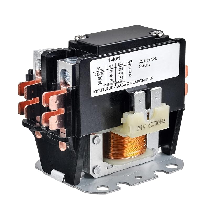
Also called a relay, the contactor acts like a switch controlled by a low-voltage signal from the thermostat. When you set your temperature, the thermostat sends a small voltage (often 24V) to the contactor coil. That activates the main contacts, allowing full house voltage (120V or 240V) to reach the compressor and fan motor.
On the diagram, the contactor appears as two sets of connected contacts: one for the control circuit (low voltage), another for the load (high voltage). You’ll see numbered terminals like L1, T1, C, etc.—these correspond to physical lugs on the actual device.
The Thermostat
Your thermostat initiates the entire process. Modern Carrier models often use electronic thermostats that send precise signals based on room temperature. In older systems, mechanical thermostats use mercury switches or bimetallic strips.
In wiring diagrams, thermostats are shown as simple switches—open when off, closed when calling for cooling. Their wires link to the control transformer (which steps down house voltage to 24V) and ultimately to the contactor coil.
The Fan Motor
The indoor blower motor circulates cooled air through your ducts. Like the compressor, it needs a capacitor (if it’s a PSC—permanent split-capacitor motor). The diagram shows whether the fan runs continuously or cycles with the compressor.
Some Carrier systems feature variable-speed fans controlled by a separate board. These appear as additional circuits with feedback loops, indicated by dashed lines or labeled “VFD” (Variable Frequency Drive).
How to Read a Carrier Air Conditioner Wiring Diagram
Now that you know the players, let’s learn to decode the playbook. Reading a wiring diagram may seem intimidating at first, but it follows a consistent pattern across all Carrier models.
Step 1: Locate the Model Number
Every Carrier air conditioner has a model number printed on a metal tag near the outdoor unit or inside the access panel. Examples include:
– **50HCB018**: Packaged rooftop unit
– **24ABC60123**: Split-system central AC
– **13SEB018**: Window or portable unit
Search online for “Carrier [model number] wiring diagram PDF” to get the official schematic. Avoid third-party sites unless verified—improper diagrams lead to costly errors.
Step 2: Identify Power Sources
Household AC units run on either 120 volts (common for smaller models) or 240 volts (standard for larger central systems). Look for symbols showing:
– Line voltage (L1, L2)
– Neutral (N)
– Ground (GND)
Most Carrier diagrams separate high-voltage (HVAC) circuits from low-voltage (control) circuits using color coding or shading. Never mix these—mixing them risks blowing transformers or damaging controls.
Step 3: Trace the Control Circuit
Start at the thermostat. Follow the path to the control transformer, then to the contactor coil. This entire loop operates at 24 volts and is much safer to handle than main power lines.
Use arrows or solid lines to track the flow. If the thermostat calls for cooling, current should complete the circuit and energize the contactor.
Step 4: Follow High-Voltage Paths
Once the contactor closes, main power flows to the compressor and fan motor. Trace these back to the breaker panel and verify wire sizes match the diagram’s specifications.
Pay attention to grounding wires—they’re usually green or bare copper and connect to the unit’s chassis or external ground rod.
Step 5: Cross-Reference Physical Connections
Compare the diagram to your actual unit. Terminal blocks often have stickers indicating wire colors. For example:
– Red = Hot (L1)
– White = Neutral (N)
– Green = Ground
If colors don’t match, consult the installation manual—sometimes carriers repurpose colors between models.
Common Wiring Mistakes (and How to Avoid Them)
Even experienced technicians make wiring errors. Here are three frequent pitfalls with Carrier systems—and how to dodge them.
Mistake #1: Mixing Up Start and Run Capacitors
This is the #1 cause of compressor burnout. Start capacitors provide brief boosts during startup; run capacitors support continuous operation. Swapping them overloads one while underloading the other.
✅ Solution: Check capacitor labels on the physical unit. If unclear, measure capacitance with a multimeter and compare to the diagram’s rating (e.g., 7.5 µF start, 50 µF run).
Mistake #2: Incorrect Wire Gauge
Using undersized wires creates resistance, leading to voltage drop and overheating. Oversized wires waste money and complicate connections.
✅ Solution: Match wire size exactly as shown in the diagram (e.g., 14 AWG for control circuits, 10 AWG for compressor leads). Use a wire gauge chart if unsure.
Mistake #3: Skipping the Ground Connection
Grounding protects against shock and stabilizes voltage. Some DIYers skip it to save time, but Carrier units require proper grounding per NEC codes.
✅ Solution: Connect green/bare wires to a grounded metal conduit or dedicated ground rod. Test continuity with a multimeter after installation.
Mistake #4: Ignoring Polarity on Capacitors and Motors
While many modern motors are non-polarized, capacitors and certain sensors require correct polarity. Reversing it reduces lifespan or causes immediate failure.
✅ Solution: Note plus/minus signs on capacitors. For motors, match phase sequence if rewiring—use a phase tester if available.
Mistake #5: Using Generic Diagrams
Assuming all Carrier 1-ton units have identical wiring? Not true! Even minor firmware differences change terminal assignments.
✅ Solution: Always download the exact diagram for your model. Carriers offer free digital copies via their dealer portal or customer support hotline.
Practical Example: Troubleshooting a No-Cooling Carrier AC
Let’s walk through a real-world scenario. Your Carrier 24ABC60123 suddenly stops cooling, though the outdoor fan spins. Here’s how to use the wiring diagram to diagnose the issue.
Observation:
– Indoor blower works
– Outdoor fan runs
– No cold air from vents
– Thermostat displays setpoint correctly
Diagnosis Using the Diagram:
1. **Check power supply**: Verify 240V at the disconnect switch using a voltmeter.
2. **Inspect contactor**: If it clicks but doesn’t close fully, clean contacts or replace.
3. **Test capacitor**: Discharge and measure—if below 80% of rated value, replace.
4. **Verify compressor windings**: Use ohmmeter to check for open circuits (infinite resistance).
5. **Examine thermostat wires**: Ensure R and Y terminals receive 24V when calling for cooling.
Using the wiring diagram, you’d trace each step logically—no trial-and-error guesswork needed. Most likely culprit? A failed run capacitor (common in Carrier units due to age), which the diagram clearly separates from the start capacitor.
Upgrading or Modifying Your Carrier System
Sometimes you need more than repair—you need enhancement. Whether adding smart thermostats, upgrading insulation, or integrating solar power, wiring modifications require careful planning.
Smart Thermostat Installation
Modern Carrier systems work seamlessly with Nest, Ecobee, or Honeywell Lyric thermostats. The wiring diagram shows where to tap into R, C, Y, G, and W wires. Note that some older models may lack a C-wire (common wire), requiring a power-stealing adapter.
Always confirm compatibility with Carrier’s website before purchasing.
Solar Integration Considerations
Solar-ready Carrier units have special wiring for microinverters or DC-powered compressors. The diagram will highlight photovoltaic inputs and bypass relays. Consult an electrician familiar with renewable energy setups—this isn’t a DIY project.
Energy-Efficient Upgrades
Adding programmable timers or zoning systems alters circuit loads. Review the diagram to ensure your breaker panel can handle the added demand. Never exceed 80% of a breaker’s capacity per NEC guidelines.
Conclusion: Empower Yourself with Knowledge
A wiring diagram for a Carrier air conditioner isn’t just paperwork—it’s your secret weapon for safe, effective HVAC management. By learning to read it, you gain confidence during installations, repairs, and upgrades. Remember: electricity is unforgiving. One wrong connection can fry your unit, spark a fire, or send you to the hospital.
But armed with the right tools—the correct diagram, a multimeter, and patience—you become more than a homeowner or technician. You become a problem-solver. You prevent wasted money on unnecessary replacements. You extend the life of your investment. And most importantly, you keep your family comfortable and safe.
So next time your Carrier AC acts up, don’t panic. Grab your diagram, put on gloves, and methodically trace the circuits. You’ve got this.
Frequently Asked Questions
Where can I find the official wiring diagram for my Carrier air conditioner?
Visit Carrier’s official website and search for your specific model number (e.g., 24ABC60123). They provide free downloadable PDFs. Alternatively, contact a Carrier-certified dealer or call customer support with your serial number.
Can I use a wiring diagram from another Carrier model?
Not recommended. Even small model variations change terminal assignments and circuit logic. Always use the diagram matching your exact unit to avoid miswiring and potential damage.
Is it safe to work on the wiring myself?
Only if you’re trained in basic electrical safety. Always shut off power at the breaker, verify with a multimeter, and never work alone. If unsure, hire an HVAC technician licensed in your area.
Why does my Carrier AC click but not cool?
This usually indicates the contactor is activating (click sound) but failing to deliver full power to the compressor—often due to a faulty capacitor, worn contacts, or low refrigerant. Refer to the wiring diagram to test each component systematically.
Do all Carrier units use the same color code for wires?
Approximately, yes—but not universally. Most use red (hot), white (neutral), blue (compressor), yellow (fan), and green (ground). However, newer models may vary, so always cross-reference with the physical unit and diagram.
How do I reset the wiring after disconnecting power?
After restoring power, wait 5–10 minutes for capacitors to discharge. Then press the “Reset” button on the control board (if equipped) or cycle the thermostat off/on. Some Carrier models auto-reset within minutes.