
Understanding the wiring diagram for Carrier air conditioner units is essential for safe installation, maintenance, and troubleshooting. This guide breaks down the components, symbols, and best practices so you can confidently work with your system—whether you’re a DIY enthusiast or a professional technician.
Key Takeaways
- Wiring diagrams are essential tools: They provide a visual roadmap of your Carrier AC’s electrical system, helping you understand how components connect and interact.
- Safety comes first: Always turn off power at the breaker before working on any electrical connections to prevent shocks or damage.
- Know the key components: Familiarize yourself with the compressor, contactor, capacitor, thermostat, and fan motor—these are central to the wiring layout.
- Use the correct symbols: Electrical schematics use standardized symbols; learning them makes reading any wiring diagram much easier.
- Follow manufacturer guidelines: Always refer to your specific Carrier model’s manual or diagram to avoid incorrect connections.
- Color codes matter: Wire colors (like red for power, white for common, green for ground) help identify functions and ensure proper connections.
- When in doubt, call a pro: Complex issues or unfamiliar wiring should be handled by a licensed HVAC technician to ensure safety and compliance.
📑 Table of Contents
- Understanding the Importance of a Wiring Diagram for Carrier Air Conditioner
- What Is a Wiring Diagram and Why Do You Need One?
- Key Components in a Carrier Air Conditioner Wiring Diagram
- How to Read a Wiring Diagram for Carrier Air Conditioner
- Common Wiring Issues and How to Troubleshoot Them
- Safety Tips When Working with Carrier AC Wiring
- Conclusion
Understanding the Importance of a Wiring Diagram for Carrier Air Conditioner
When it comes to maintaining or repairing your Carrier air conditioner, few tools are as valuable as a wiring diagram. Think of it as the electrical blueprint of your system—a detailed map that shows how every wire, switch, and component connects to keep your AC running smoothly. Whether you’re installing a new unit, replacing a faulty part, or simply troubleshooting a cooling issue, having access to the correct wiring diagram for Carrier air conditioner models can save you time, money, and frustration.
Carrier is one of the most trusted names in HVAC systems, known for their reliability and advanced technology. But like any complex machine, their air conditioners rely on a network of electrical components working in harmony. From the thermostat that senses room temperature to the compressor that pumps refrigerant, each part must be properly wired to function. A wiring diagram helps you visualize this network, making it easier to identify where a problem might be occurring—like a blown fuse, a stuck contactor, or a miswired thermostat.
But why is this so important? For one, electrical work on HVAC systems can be dangerous if not done correctly. A single wrong connection can damage your unit, trip breakers, or even pose a fire hazard. That’s why understanding the wiring diagram isn’t just helpful—it’s essential for safety. Whether you’re a homeowner trying to fix a minor issue or a technician performing routine maintenance, knowing how to read and interpret the wiring diagram for Carrier air conditioner units ensures that repairs are done right the first time.
What Is a Wiring Diagram and Why Do You Need One?
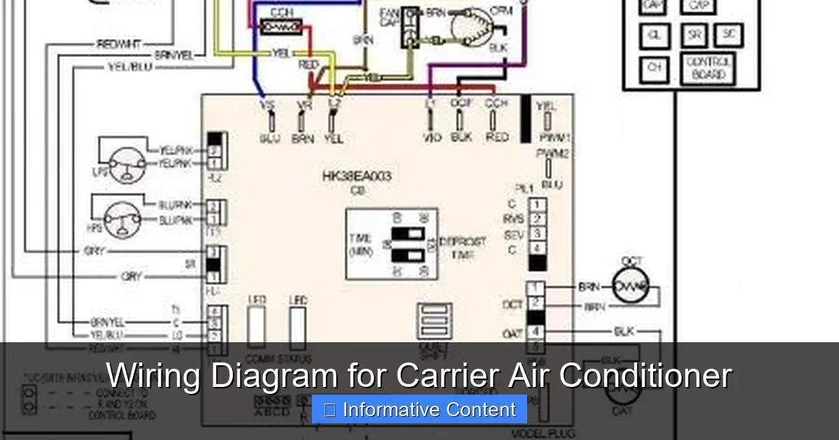
Visual guide about Wiring Diagram for Carrier Air Conditioner
Image source: tankbig.com
A wiring diagram is a simplified visual representation of an electrical circuit. Unlike a physical layout that shows where wires are run through walls or ducts, a wiring diagram focuses on the logical connections between components. It uses standardized symbols to represent parts like motors, switches, relays, and capacitors, and lines to show how they’re connected. For Carrier air conditioners, these diagrams are typically included in the installation manual or service guide that comes with the unit.
So, why do you need one? Let’s say your air conditioner suddenly stops cooling. You check the thermostat—it’s set correctly. The breaker hasn’t tripped. The air filter is clean. What’s next? Without a wiring diagram, you’re essentially guessing. But with one, you can trace the electrical path from the thermostat to the outdoor unit, checking each connection along the way. You might discover that the contactor isn’t engaging, or that the capacitor has failed. The diagram helps you pinpoint the issue quickly and accurately.
Another common scenario is during installation. If you’re replacing an old AC unit with a new Carrier model, the wiring may not match exactly. The new unit might have different voltage requirements, additional safety switches, or updated control boards. The wiring diagram for Carrier air conditioner models will show you exactly how to connect the new system to your home’s electrical supply and thermostat wiring. This ensures compatibility and prevents costly mistakes.
Even for routine maintenance, a wiring diagram is useful. For example, if you’re cleaning the condenser coils or inspecting the fan motor, knowing how the power flows through the system helps you safely disconnect and reconnect components. It also helps you understand how the system operates under different conditions—like when it switches from cooling to defrost mode in a heat pump system.
Key Components in a Carrier Air Conditioner Wiring Diagram
To make sense of a wiring diagram for Carrier air conditioner units, you need to understand the main components involved. Each plays a critical role in the system’s operation, and the diagram shows how they’re electrically connected. Let’s break down the most important ones.
Thermostat
The thermostat is the brain of your HVAC system. It senses the room temperature and sends signals to the air conditioner to turn on or off. In the wiring diagram, the thermostat is usually shown on the left side, connected to low-voltage wires (typically 24 volts) that run to the indoor unit. Common wire colors include red (R – power), white (W – heat), yellow (Y – cooling), green (G – fan), and sometimes blue or black (C – common). These wires carry control signals, not high voltage, so they’re safe to handle with the power off.
Contactor
The contactor is an electromagnetic switch that controls power to the compressor and condenser fan motor. When the thermostat calls for cooling, it sends a signal to the contactor, which closes and allows high-voltage electricity to flow to the outdoor unit. In the diagram, the contactor is often represented as a coil with two large terminals. If the contactor fails, the outdoor unit won’t turn on, even if the thermostat is working. A common sign of a bad contactor is a humming sound from the outdoor unit without the compressor starting.
Compressor
The compressor is the heart of the air conditioning system. It pumps refrigerant through the coils to remove heat from your home. In the wiring diagram, the compressor is usually connected to the contactor and protected by a high-pressure switch and a thermal overload. It’s powered by 240 volts in most residential systems, so it’s critical to ensure the wiring is secure and the correct gauge. A faulty compressor may not show up on the diagram directly, but issues like locked rotor amps or overheating can be traced back to wiring problems.
Capacitor
The capacitor stores electrical energy and helps start the compressor and fan motors. There are usually two types: a start capacitor (used briefly during startup) and a run capacitor (used continuously). In the diagram, capacitors are shown as cylinders with two or three terminals. If your AC starts slowly or the fan motor struggles to turn, a bad capacitor is often the culprit. Replacing it is relatively simple, but you must discharge it first to avoid electric shock.
Fan Motor
The condenser fan motor cools the outdoor unit by blowing air over the coils. It’s typically a single-phase motor connected to the contactor and capacitor. In the wiring diagram, it’s shown with wires labeled L1, L2, and sometimes a ground. If the fan doesn’t spin, check the capacitor, wiring, and motor windings. A seized motor may draw too much current and trip the breaker.
Transformer
The transformer steps down the high-voltage power (usually 240V) to 24V, which is used to power the thermostat and control board. It’s a small, rectangular component often mounted near the indoor unit. In the diagram, it’s shown with primary (high-voltage) and secondary (low-voltage) windings. If the thermostat isn’t getting power, the transformer could be faulty.
Control Board
Modern Carrier units often have a control board that manages timing, safety switches, and communication between components. It’s the central hub of the system and is shown in the diagram with multiple input and output connections. If the board fails, the entire system may not operate, even if individual components are working.
How to Read a Wiring Diagram for Carrier Air Conditioner
Reading a wiring diagram might seem intimidating at first, but once you understand the basics, it becomes much easier. The key is to break it down into manageable parts and follow the flow of electricity from the power source to the components.
Start with the Power Source
Every diagram begins with the power source—usually a 240-volt circuit from your home’s breaker panel. This is shown as two hot wires (L1 and L2) and a ground. The power flows through a disconnect switch (a safety device mounted near the outdoor unit) and then to the contactor. Always ensure the disconnect is turned off before working on the system.
Follow the Control Circuit
The control circuit operates at 24 volts and includes the thermostat, transformer, and control board. The transformer converts 240V to 24V, which powers the thermostat. When you set the thermostat to “cool,” it closes the Y (cooling) and G (fan) circuits, sending a signal to the indoor unit. The indoor unit then sends a signal to the outdoor unit via the Y wire, telling the contactor to close.
Trace the High-Voltage Circuit
Once the contactor closes, 240V power flows to the compressor and fan motor. This is the high-voltage circuit, and it’s critical to handle it with care. The diagram will show how the power splits between the compressor and fan, often through separate fuses or breakers. Some systems also include a reversing valve (for heat pumps) or a defrost control board.
Use Wire Colors as Guides
Wire colors are standardized to help you identify their function. Here’s a quick reference:
– Red: 24V power (R wire)
– White: Heat signal (W wire)
– Yellow: Cooling signal (Y wire)
– Green: Fan signal (G wire)
– Blue or Black: Common (C wire)
– Black or Red (heavy gauge): 240V power (L1 and L2)
– Green or Bare: Ground
These colors make it easier to trace connections and verify that wires are connected correctly.
Look for Symbols and Labels
Electrical symbols are universal. For example:
– A circle with an “M” inside represents a motor.
– A zigzag line is a resistor.
– Two parallel lines with a gap is a capacitor.
– A coil with two contacts is a relay or contactor.
Labels like “C,” “NO,” or “NC” indicate common, normally open, or normally closed contacts. Understanding these symbols helps you interpret the diagram accurately.
Practice with a Sample Diagram
To get comfortable, try tracing a simple diagram step by step. Start at the thermostat, follow the Y wire to the outdoor unit, and see how it activates the contactor. Then trace the 240V path from the contactor to the compressor. With practice, you’ll be able to read any wiring diagram for Carrier air conditioner models with confidence.
Common Wiring Issues and How to Troubleshoot Them
Even with a good wiring diagram, problems can arise. Here are some common issues and how to fix them using the diagram as your guide.
Air Conditioner Won’t Turn On
If your Carrier AC doesn’t respond when you set the thermostat to cool, start by checking the breaker and disconnect switch. If both are on, use the diagram to trace the control circuit. Check if the thermostat is sending 24V to the Y and G terminals. Use a multimeter to test for voltage. If there’s no signal, the thermostat or transformer may be faulty.
Outdoor Unit Runs but Doesn’t Cool
This could mean the compressor isn’t starting. Check the contactor—does it click when the thermostat calls for cooling? If not, the control signal may be missing. If it clicks but the compressor doesn’t start, test the capacitor and check for proper voltage at the compressor terminals. A bad capacitor is a common cause.
Fan Motor Doesn’t Spin
If the fan motor is silent, check the capacitor first. A swollen or leaking capacitor needs replacement. Also, verify that 240V is reaching the motor terminals. If the motor hums but doesn’t turn, it may be seized and need replacement.
Thermostat Not Working
If the thermostat display is blank, check the C (common) wire connection. Without a common wire, the thermostat can’t get power. Also, test the transformer output—it should read around 24V AC. If it’s low or zero, the transformer may be bad.
Frequent Breaker Tripping
This usually indicates an overload or short circuit. Use the diagram to check for loose connections, damaged wires, or a failing compressor. A compressor drawing too many amps can trip the breaker. Use an ammeter to measure current draw and compare it to the nameplate rating.
Incorrect Wiring During Installation
If you’re installing a new unit and the system doesn’t work, double-check the wiring against the diagram. Common mistakes include swapping L1 and L2, reversing the Y and G wires, or forgetting the ground. Always label wires before disconnecting the old unit.
Safety Tips When Working with Carrier AC Wiring
Electrical work on HVAC systems can be dangerous. Follow these safety tips to protect yourself and your equipment.
Turn Off the Power
Always shut off the power at the main breaker and the disconnect switch before working on any wiring. Use a voltage tester to confirm that power is off.
Use Proper Tools
Use insulated tools and wear rubber-soled shoes. A non-contact voltage tester can help detect live wires without touching them.
Don’t Bypass Safety Devices
Never remove fuses, breakers, or pressure switches to force the system to run. These devices protect against overheating and overpressure.
Follow Local Codes
Electrical work must comply with local building and electrical codes. If you’re unsure, consult a licensed electrician or HVAC technician.
When to Call a Professional
If you’re not confident in your ability to read the wiring diagram or perform electrical work, don’t take the risk. Complex issues like compressor replacement, control board diagnostics, or refrigerant handling should be left to professionals.
Conclusion
Understanding the wiring diagram for Carrier air conditioner units is a valuable skill that empowers you to maintain, troubleshoot, and repair your system safely and effectively. From identifying key components like the contactor and capacitor to tracing electrical paths and diagnosing common issues, the diagram serves as your guide through the complex world of HVAC wiring. Whether you’re a homeowner tackling a simple repair or a technician performing routine service, this knowledge ensures that your Carrier AC runs efficiently and reliably for years to come.
Remember, safety is paramount. Always turn off the power, use the correct tools, and refer to your specific model’s diagram. And when in doubt, don’t hesitate to call a qualified HVAC professional. With the right approach, you can keep your home cool and comfortable—all thanks to a clear understanding of your system’s wiring.
Frequently Asked Questions
Where can I find the wiring diagram for my Carrier air conditioner?
The wiring diagram is usually included in the installation or service manual that came with your unit. You can also find it online by searching for your specific model number on Carrier’s official website or HVAC parts retailers.
Can I use a wiring diagram from a different Carrier model?
No, wiring diagrams are model-specific. Even small differences in components or control boards can lead to incorrect connections. Always use the diagram for your exact model to ensure safety and proper operation.
What tools do I need to read a wiring diagram?
You’ll need a multimeter to test voltage and continuity, a non-contact voltage tester for safety, and basic hand tools like screwdrivers and wire strippers. A good understanding of electrical symbols is also essential.
Is it safe to work on AC wiring myself?
If you have basic electrical knowledge and follow safety procedures, simple tasks like replacing a capacitor or checking connections can be safe. However, high-voltage work or complex diagnostics should be handled by a licensed technician.
What does a red wire usually mean in a Carrier AC wiring diagram?
In most Carrier systems, the red wire carries 24V power from the transformer to the thermostat (R wire). It’s part of the low-voltage control circuit and is essential for thermostat operation.
Why is my Carrier AC not turning on even though the thermostat is set?
This could be due to a tripped breaker, faulty thermostat, bad contactor, or wiring issue. Use the wiring diagram to trace the control circuit and check for 24V at the Y and G terminals when cooling is called for.