
Understanding a Carrier air conditioner wiring schematic is crucial for safe installation, troubleshooting, and maintenance. This guide breaks down the components, symbols, and best practices to help you interpret these diagrams with confidence.
Key Takeaways
- Wiring schematics are essential blueprints: They show how electrical components connect and interact in your Carrier AC unit.
- Know the symbols: Familiarize yourself with standard electrical symbols like capacitors, relays, and transformers used in Carrier systems.
- Color coding matters: Wire colors indicate function—red for power, white for common, yellow for compressor, etc.
- Safety first: Always turn off power at the breaker before working on any wiring.
- Use the correct manual: Always refer to the specific model’s installation and service manual for accurate schematics.
- Common issues stem from miswiring: Loose connections or crossed wires can cause system failure or safety hazards.
- Professional help is recommended: If you’re unsure, consult a licensed HVAC technician to avoid damage or injury.
📑 Table of Contents
- Introduction to Carrier Air Conditioner Wiring Schematics
- What Is a Wiring Schematic and Why Is It Important?
- Understanding Common Symbols in Carrier Wiring Schematics
- Key Components in a Carrier AC Wiring Schematic
- Common Wiring Issues and How to Fix Them
- Safety Tips When Working with Wiring Schematics
- When to Call a Professional
- Conclusion
Introduction to Carrier Air Conditioner Wiring Schematics
When it comes to maintaining or repairing your Carrier air conditioner, few tools are as important as the wiring schematic. Think of it as the unit’s electrical blueprint—a detailed map that shows how every wire, switch, and component connects to keep your system running smoothly. Whether you’re a seasoned HVAC technician or a homeowner trying to understand why your AC isn’t turning on, knowing how to read a Carrier air conditioner wiring schematic can save you time, money, and frustration.
Carrier, one of the most trusted names in heating and cooling, designs its systems with precision and reliability in mind. But even the best systems can develop electrical issues over time. That’s where the wiring schematic comes in. It helps you trace circuits, identify faulty components, and ensure that repairs are done correctly. Without this diagram, diagnosing problems becomes a guessing game—one that could lead to further damage or even safety risks.
In this guide, we’ll walk you through everything you need to know about Carrier air conditioner wiring schematics. From understanding basic symbols to interpreting complex circuits, you’ll gain the knowledge to approach your AC system with confidence. We’ll also cover common wiring issues, safety tips, and when it’s best to call in a professional. By the end, you’ll be equipped to read, interpret, and troubleshoot these essential diagrams like a pro.
What Is a Wiring Schematic and Why Is It Important?
Visual guide about Carrier Air Conditioner Wiring Schematic
Image source: i.ytimg.com
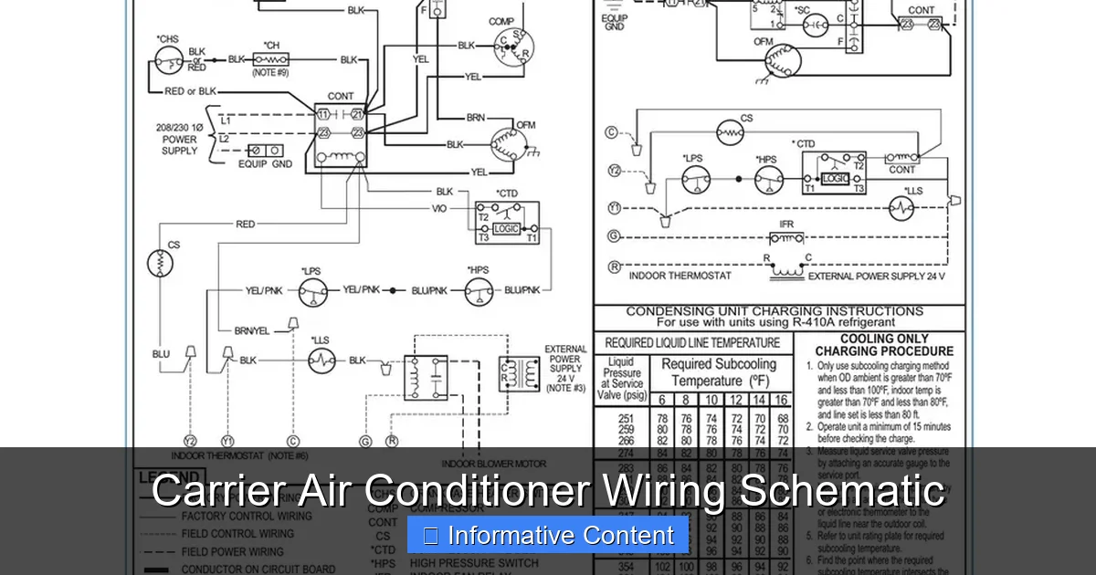
A wiring schematic, also known as a wiring diagram or electrical schematic, is a visual representation of an electrical circuit. It uses standardized symbols to depict components such as motors, capacitors, relays, transformers, and switches, along with the wires that connect them. In the context of a Carrier air conditioner, the schematic shows how power flows from the main electrical panel through the thermostat, control board, compressor, fan motors, and other key parts.
Why is this so important? First, it provides clarity. When your AC stops working, the schematic helps you pinpoint where the problem might be. For example, if the indoor fan isn’t running, you can use the diagram to trace the circuit from the thermostat to the fan motor, checking each connection along the way. Second, it ensures safety. Working on electrical systems without understanding the wiring can lead to shocks, short circuits, or even fires. The schematic acts as a guide to help you avoid these dangers.
Third, it supports proper installation. If you’re replacing a component or installing a new unit, the wiring schematic ensures everything is connected correctly. Even small mistakes—like swapping a red and yellow wire—can prevent the system from functioning or cause damage over time. Finally, it aids in compliance with local electrical codes. Many jurisdictions require that HVAC installations follow manufacturer specifications, which are detailed in the schematic.
How Wiring Schematics Differ from Other Diagrams
It’s easy to confuse a wiring schematic with other types of diagrams, such as a parts diagram or a piping layout. But they serve different purposes. A parts diagram shows the physical location of components inside the unit, while a piping layout focuses on refrigerant lines. The wiring schematic, on the other hand, is purely electrical. It doesn’t show where parts are located in space, but rather how they’re connected electrically.
For example, a parts diagram might show that the capacitor is mounted near the compressor, but the wiring schematic will show that the capacitor is connected to the compressor’s start and run windings. This distinction is crucial when troubleshooting. If the compressor isn’t starting, you need to know not just where the capacitor is, but how it’s wired into the circuit.
Another key difference is that wiring schematics use abstract symbols rather than realistic images. A resistor might look like a zigzag line, a capacitor like two parallel lines, and a motor like a circle with an “M” inside. These symbols are standardized across the industry, so once you learn them, you can read schematics for any brand—not just Carrier.
Where to Find the Wiring Schematic
The wiring schematic for your Carrier air conditioner is typically found in one of three places. First, it’s included in the installation and service manual that comes with the unit. This manual is usually tucked inside the outdoor condenser unit or provided as a digital download from Carrier’s website. Second, many Carrier units have a laminated copy of the schematic attached to the inside of the electrical panel door. This is especially helpful during maintenance or repairs.
Third, you can access schematics online through Carrier’s official support portal. Simply enter your model number, and you’ll find downloadable PDFs of the manual, including the wiring diagram. Always make sure you’re looking at the correct schematic for your specific model and serial number. Even small variations between models can result in different wiring configurations.
Pro tip: Take a photo of the schematic with your phone and store it in a cloud folder. That way, you’ll always have it on hand, even if the physical copy gets damaged or lost.
Understanding Common Symbols in Carrier Wiring Schematics
To read a Carrier air conditioner wiring schematic, you need to understand the symbols used. These symbols are part of a universal language that electricians and HVAC technicians use worldwide. While they may look like abstract drawings, each one represents a real component in your system.
Let’s break down some of the most common symbols you’ll encounter:
– Power Source (L1, L2, Neutral): These are the main electrical inputs. L1 and L2 represent the two hot legs of 240V power, while the neutral (usually white) completes the circuit for 120V components.
– Transformer: Looks like two coils side by side. It steps down 240V to 24V for the thermostat and control board.
– Thermostat: Often shown as a rectangle with terminals labeled R, C, Y, G, W, etc. These correspond to power, common, cooling, fan, and heating circuits.
– Contactor: A switch that controls power to the compressor and condenser fan. It looks like a rectangle with a coil and contacts.
– Capacitor: Two parallel lines (run capacitor) or two lines with a curved line (start capacitor). Stores energy to help motors start and run efficiently.
– Motor: A circle with an “M” inside. Represents the compressor, condenser fan, or indoor blower motor.
– Relay: Similar to a contactor but smaller. Used to control low-power circuits.
– Fuse or Circuit Breaker: A line with a break and a symbol inside. Protects the circuit from overcurrent.
– Ground: A series of horizontal lines decreasing in length. Indicates the grounding point for safety.
Decoding Wire Colors and Labels
In addition to symbols, wiring schematics use color codes and labels to identify wires. Carrier follows standard HVAC color conventions, but it’s always good to double-check your specific model.
Here’s a quick reference:
– Red (R): 24V power from the transformer to the thermostat.
– White (W): Heat signal (used in heat pumps or furnaces).
– Yellow (Y): Cooling signal—activates the compressor and condenser fan.
– Green (G): Fan signal—turns on the indoor blower.
– Blue or Brown (C): Common wire—completes the 24V circuit.
– Orange (O): Reversing valve in heat pumps—switches between cooling and heating.
– Black or Red (L1, L2): 240V power lines to the compressor and fan motors.
These colors help you trace circuits quickly. For example, if the thermostat calls for cooling (Y), power flows through the yellow wire to the contactor, which then sends 240V to the compressor. If the compressor doesn’t start, you can check for voltage at the yellow wire and then at the contactor.
Labels like “C,” “R,” “Y,” and “G” are also used on terminal strips and components. Always match these labels when connecting wires. Swapping a Y and G wire, for instance, could cause the fan to run when the compressor is off—leading to inefficient cooling.
Practical Example: Tracing a Cooling Circuit
Let’s walk through a real-world example. Suppose your Carrier AC turns on, but the compressor doesn’t start. Using the wiring schematic, here’s how you’d troubleshoot:
1. Check the thermostat: Ensure it’s set to “Cool” and the fan is on “Auto.”
2. Look at the schematic: Find the Y (yellow) wire from the thermostat to the control board.
3. Verify voltage: Use a multimeter to check for 24V between Y and C at the thermostat. If present, the thermostat is working.
4. Trace to the contactor: The Y signal should activate the contactor coil. Check for 24V at the coil terminals.
5. If the coil has power but the contactor doesn’t click, the contactor may be faulty.
6. If the contactor clicks, check for 240V at the compressor terminals (L1 and L2). If no voltage, the contactor contacts may be burned.
7. If voltage is present but the compressor doesn’t start, check the capacitor and windings.
This step-by-step approach, guided by the schematic, helps you isolate the problem without guessing.
Key Components in a Carrier AC Wiring Schematic
Now that you understand the symbols and colors, let’s dive into the main components you’ll see in a Carrier air conditioner wiring schematic. Each plays a vital role in the system’s operation.
The Control Board
The control board is the brain of the system. It receives signals from the thermostat and sends commands to other components. In the schematic, it’s usually shown as a rectangle with multiple input and output terminals. It manages functions like fan speed, defrost cycles (in heat pumps), and safety lockouts.
Common issues with the control board include burnt traces, failed relays, or corrupted firmware. If multiple components aren’t working, the control board is a likely suspect. Always check for power and ground connections first.
The Contactor
The contactor is a high-voltage switch that connects the compressor and condenser fan to the 240V power supply. When the thermostat calls for cooling, the contactor coil energizes, closing the contacts and allowing current to flow.
A faulty contactor may not close fully, causing the compressor to hum but not start. Over time, the contacts can burn out from arcing. Replacement is straightforward—just match the voltage and current ratings.
Capacitors
Capacitors store electrical energy and release it to help motors start and run. Carrier systems typically use two types: a run capacitor (for continuous operation) and a start capacitor (for initial boost). Some newer models use a dual-run capacitor that serves both functions.
A swollen or leaking capacitor is a clear sign of failure. Use a multimeter with a capacitance setting to test it. Never touch the terminals—capacitors can hold a charge even when power is off.
Motors
Your Carrier AC has at least two motors: the compressor (inside the outdoor unit) and the condenser fan. The indoor unit has a blower motor. Each motor has specific wiring requirements, often involving capacitors and relays.
If a motor doesn’t run, check for voltage, then test the capacitor and windings. A common issue is a seized fan blade, which prevents the motor from turning.
Thermostat and Low-Voltage Wiring
The thermostat controls the entire system using low-voltage (24V) signals. The wiring schematic shows how the R (power), C (common), Y (cooling), G (fan), and other wires connect from the thermostat to the control board.
A broken or disconnected wire can cause the system to malfunction. For example, a missing C wire means the thermostat can’t complete the circuit, leading to intermittent operation or battery drain.
Common Wiring Issues and How to Fix Them
Even with a perfect schematic, wiring problems can occur. Here are some of the most common issues and how to address them.
Loose or Corroded Connections
Over time, vibrations and temperature changes can loosen wire connections. Corrosion can also build up, especially in outdoor units. This leads to poor conductivity and intermittent operation.
Solution: Turn off power, inspect all terminals, and tighten connections. Use a wire brush to clean corrosion. Apply dielectric grease to prevent future buildup.
Incorrect Wire Sizing
Using wires that are too small can cause overheating and voltage drop. This is especially dangerous with high-current components like the compressor.
Solution: Always follow the manufacturer’s specifications for wire gauge. For 240V lines, 10 or 12 AWG is typical, depending on the unit’s amperage.
Crossed or Mislabeled Wires
During installation or repair, wires can be swapped. For example, connecting the Y wire to the G terminal will cause the fan to run continuously.
Solution: Double-check the schematic and label each wire before disconnecting. Use colored tape to mark wires if needed.
Failed Components
Capacitors, contactors, and relays wear out over time. A failed component can mimic a wiring issue.
Solution: Test each component individually. Replace any that show signs of damage or fail electrical tests.
Grounding Problems
Improper grounding can cause shocks or damage to electronics. The schematic shows where ground wires should connect.
Solution: Ensure all ground wires are securely attached to the chassis and the main ground terminal.
Safety Tips When Working with Wiring Schematics
Electrical work can be dangerous. Always prioritize safety when using a Carrier air conditioner wiring schematic.
– Turn off power: Shut off the breaker at the main panel and verify with a voltage tester.
– Use insulated tools: Prevents accidental shorts.
– Wear protective gear: Gloves and safety glasses are essential.
– Don’t work alone: Have someone nearby in case of emergency.
– Follow local codes: Some repairs require a licensed electrician.
– Never bypass safety devices: Fuses and breakers protect against fire.
If you’re unsure about any step, stop and consult a professional. It’s better to pay for expert help than risk injury or damage.
When to Call a Professional
While understanding wiring schematics is valuable, there are times when you should call a licensed HVAC technician.
– You’re not comfortable working with electricity.
– The problem involves refrigerant lines or gas furnaces.
– The unit is under warranty—DIY repairs may void it.
– You’ve tried troubleshooting but the issue persists.
– You notice burning smells, sparks, or smoke.
A professional has the tools, training, and experience to diagnose and fix complex issues safely.
Conclusion
A Carrier air conditioner wiring schematic is more than just a diagram—it’s a powerful tool for understanding, maintaining, and repairing your cooling system. By learning to read the symbols, trace circuits, and identify components, you can tackle many common issues with confidence. Remember to always prioritize safety, use the correct manual for your model, and don’t hesitate to seek professional help when needed.
Whether you’re a homeowner trying to save on repair costs or an aspiring HVAC technician, mastering wiring schematics is a skill that pays off. With practice, you’ll be able to interpret these diagrams quickly and accurately, keeping your Carrier AC running efficiently for years to come.
Frequently Asked Questions
Where can I find the wiring schematic for my Carrier air conditioner?
The wiring schematic is usually included in the installation and service manual, attached inside the electrical panel, or available for download on Carrier’s official website using your model number.
What do the wire colors mean in a Carrier AC schematic?
Standard colors include red for 24V power (R), yellow for cooling (Y), green for fan (G), white for heat (W), and blue or brown for common (C). These help identify circuit functions.
Can I repair my Carrier AC using just the wiring schematic?
The schematic helps with troubleshooting, but you also need tools like a multimeter and knowledge of electrical safety. For complex issues, professional help is recommended.
What does a failed capacitor look like on a wiring schematic?
The schematic shows the capacitor symbol, but physical signs of failure include swelling, leaking, or a burnt smell. Testing with a multimeter confirms if it needs replacement.
Why is the C wire important in the thermostat circuit?
The C (common) wire completes the 24V circuit, allowing the thermostat to operate without batteries. Without it, the thermostat may lose power or function intermittently.
Can I use a wiring schematic from a different Carrier model?
No. Wiring configurations vary by model and serial number. Always use the schematic specific to your unit to avoid miswiring and potential damage.