
A Carrier air conditioner wiring diagram is a vital tool for understanding your unit’s electrical system, diagnosing issues, and ensuring safe repairs or installations. Whether you’re a homeowner or technician, knowing how to interpret these diagrams helps prevent mistakes and improves system efficiency.
Key Takeaways
- Wiring diagrams are essential for safe troubleshooting: They show how components connect electrically, helping you avoid shocks or damage.
- Carrier diagrams use standardized symbols: Learning common symbols like capacitors, relays, and transformers makes reading any model easier.
- Always turn off power before working: Safety is critical—shut off the breaker and verify with a multimeter before touching wires.
- Match the diagram to your exact model: Wiring can vary between Carrier units; always use the manual for your specific serial number.
- Color codes matter: Wire colors indicate function (e.g., red for power, white for common), so follow them closely.
- Use diagrams for installation and repair: Whether installing a new unit or fixing a faulty compressor, the wiring diagram guides correct connections.
- Consult a professional if unsure: Complex issues like control board failures should be handled by licensed HVAC technicians.
📑 Table of Contents
- Understanding the Importance of a Carrier Air Conditioner Wiring Diagram
- What Is a Carrier Air Conditioner Wiring Diagram?
- How to Read a Carrier Air Conditioner Wiring Diagram
- Safety Precautions When Working with Wiring Diagrams
- Troubleshooting Common Issues Using the Wiring Diagram
- Where to Find Your Carrier Wiring Diagram
- When to Call a Professional
- Conclusion
Understanding the Importance of a Carrier Air Conditioner Wiring Diagram
When your air conditioner stops cooling or won’t turn on at all, the first instinct might be to call a technician. But what if you could diagnose the problem yourself? That’s where a Carrier air conditioner wiring diagram comes in. These detailed schematics are more than just technical drawings—they’re your roadmap to understanding how your AC unit works electrically.
Think of the wiring diagram as the unit’s electrical blueprint. It shows how every component—from the compressor and fan motor to the thermostat and control board—connects and communicates. Whether you’re installing a new system, replacing a part, or troubleshooting a malfunction, this diagram helps you avoid guesswork. Without it, you risk miswiring, damaging components, or even creating a fire hazard.
Carrier, one of the most trusted names in HVAC, designs its systems with precision and reliability in mind. But like any complex machine, things can go wrong. A loose wire, a blown fuse, or a faulty relay can disrupt the entire system. The wiring diagram helps you pinpoint exactly where the issue lies. It’s not just for professionals—homeowners with basic electrical knowledge can use it safely, as long as they follow proper precautions.
What Is a Carrier Air Conditioner Wiring Diagram?
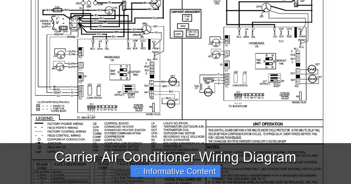
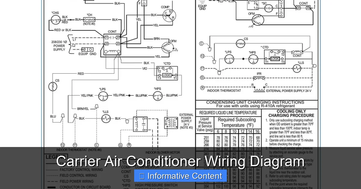
Visual guide about Carrier Air Conditioner Wiring Diagram
Image source: i2.wp.com
A Carrier air conditioner wiring diagram is a visual representation of the electrical connections within your AC unit. It uses standardized symbols and color codes to show how power flows through the system and how components interact. Unlike a physical layout diagram (which shows where parts are located), a wiring diagram focuses purely on electrical pathways.
These diagrams are typically found in the installation and service manual that comes with your Carrier unit. They’re also available online through Carrier’s official support portal or third-party HVAC resource sites. Each model—whether it’s a 24ACC6, 38MURA, or 40RUM—has its own unique diagram, so it’s crucial to use the correct one for your specific unit.
The diagram includes several key elements:
– **Power supply lines** (usually 240V for the compressor and 120V for controls)
– **Control circuits** (low-voltage wiring from the thermostat)
– **Component symbols** (like motors, capacitors, contactors, and relays)
– **Wire colors and labels** (to identify connections)
– **Grounding points** (for safety)
For example, a typical diagram might show the red wire carrying 24V from the thermostat to the contactor, which then energizes the compressor. The white wire might return as the common (C) wire, completing the circuit. Understanding these basics allows you to trace power flow and identify breaks or faults.
Common Symbols Used in Carrier Wiring Diagrams
Carrier wiring diagrams rely on universal electrical symbols, but it helps to know the most common ones. Here’s a quick guide:
– **Resistor**: A zigzag line indicating resistance in the circuit.
– **Capacitor**: Two parallel lines (or one curved and one straight) showing energy storage.
– **Relay**: A coil with switch contacts, used to control high-power devices.
– **Contactor**: A switch that turns the compressor and fan on/off.
– **Transformer**: Two coils linked by a core, stepping down voltage (e.g., 240V to 24V).
– **Motor**: A circle with an “M” inside, representing fan or compressor motors.
– **Thermostat**: Often shown as a box with terminals labeled R, W, Y, G, C.
– **Ground**: A series of descending lines or a triangle symbol.
These symbols are consistent across most Carrier models, making it easier to learn once and apply to multiple units. Many manuals include a legend or symbol key to help you decode the diagram.
Wire Color Codes and Their Meanings
Wire color is not random—it follows industry standards to indicate function. In Carrier systems, you’ll commonly see:
– **Red**: 24V power from the transformer (often the “R” terminal on the thermostat)
– **White**: Common wire (“C” terminal), completing the 24V circuit
– **Yellow**: Controls the compressor (“Y” terminal)
– **Green**: Controls the indoor fan (“G” terminal)
– **Blue or Orange**: Used for heat pumps (“O” for reversing valve)
– **Brown**: Often used for auxiliary heat or secondary circuits
– **Black**: High-voltage power (240V to compressor and fan)
Always double-check your specific diagram, as colors can vary slightly between models. Never assume—verify with a multimeter if you’re unsure.
How to Read a Carrier Air Conditioner Wiring Diagram
Reading a wiring diagram might seem intimidating at first, but it’s like learning a new language—once you know the basics, it becomes second nature. Start by identifying the main sections: power supply, control circuit, and load devices.
Begin with the **power source**. Look for the 240V line coming into the unit, usually labeled L1 and L2. This powers the compressor and outdoor fan. Next, find the **transformer**, which steps down the voltage to 24V for the control circuit. The transformer’s secondary side connects to the thermostat wires.
Now, trace the **control circuit**. This is the low-voltage side (24V) that tells the system what to do. The thermostat sends signals through wires like Y (cooling), G (fan), and W (heating). These signals activate relays or contactors, which then switch the high-voltage components on.
For example, when you set your thermostat to “cool,” it closes the Y and G circuits. The Y signal energizes the contactor, turning on the compressor. The G signal turns on the indoor fan. The diagram shows exactly how these connections are made.
Step-by-Step Guide to Tracing a Circuit
Let’s walk through a practical example. Suppose your outdoor fan isn’t running. Here’s how to use the wiring diagram to find the issue:
1. **Turn off power** at the breaker and verify with a multimeter.
2. **Locate the fan motor** on the diagram. It’s usually labeled “ODF” (outdoor fan).
3. **Find the power source**—typically 240V from L1 and L2.
4. **Identify the contactor**—a switch that controls power to the fan.
5. **Check the control signal**—does the thermostat send 24V to the contactor coil when cooling is called?
6. **Test continuity**—use a multimeter to check if the contactor is receiving power and if the fan motor has resistance.
If the contactor isn’t engaging, the issue could be a faulty thermostat, broken wire, or bad contactor. The diagram helps you isolate the problem without guessing.
Using the Diagram for Installation
Wiring diagrams are equally valuable during installation. Whether you’re replacing an old unit or setting up a new one, the diagram ensures all connections are correct.
For instance, when connecting the thermostat, the diagram shows which wire goes to which terminal. Miswiring can cause the system to run constantly, not turn on, or even damage the control board. The diagram also highlights grounding requirements and wire gauge specifications.
Always follow the manufacturer’s instructions and local electrical codes. If you’re not confident, hire a licensed electrician or HVAC technician. A small mistake can lead to big problems.
Safety Precautions When Working with Wiring Diagrams
Electricity is unforgiving. Even low-voltage circuits can cause injury, and high-voltage lines can be deadly. Before touching any wires, follow these safety steps:
– **Turn off the power** at the main breaker and the disconnect switch near the unit.
– **Use a non-contact voltage tester** to confirm no power is present.
– **Wear insulated gloves and safety glasses**.
– **Never work alone**—have someone nearby in case of emergency.
– **Keep the area dry**—water and electricity don’t mix.
Even with the diagram, don’t assume you know everything. If a wire looks damaged, a component smells burnt, or you’re unsure about a connection, stop and consult a professional.
Common Mistakes to Avoid
Many DIYers make simple errors that lead to bigger issues. Here are a few to watch out for:
– **Assuming wire colors are universal**: While red is usually power, always verify with the diagram.
– **Skipping the multimeter test**: Visual inspection isn’t enough—test for voltage and continuity.
– **Reversing L1 and L2**: This can damage the compressor or fan motor.
– **Overlooking grounding**: Improper grounding can cause shocks or equipment failure.
– **Using incorrect wire gauge**: Undersized wires can overheat and cause fires.
Taking your time and double-checking every step prevents costly mistakes.
Troubleshooting Common Issues Using the Wiring Diagram
The wiring diagram is your best friend when diagnosing problems. Here are some common issues and how to solve them using the diagram.
Unit Won’t Turn On
If the AC doesn’t respond at all, start with the power supply. Check the breaker and fuse. Then, use the diagram to trace the 24V control circuit. Is the transformer outputting 24V? Is the thermostat sending a signal? If not, the issue could be a bad thermostat, blown fuse, or faulty transformer.
Compressor Runs but Fan Doesn’t
This often points to a fan motor or capacitor issue. Use the diagram to locate the fan circuit. Test the capacitor with a multimeter—if it’s bulging or not holding a charge, replace it. Also, check the fan motor for continuity. A seized motor may need replacement.
Short Cycling (Frequent On/Off)
Short cycling can be caused by low refrigerant, dirty coils, or electrical issues. Use the diagram to check the pressure switch and control board connections. A faulty pressure switch might be opening the circuit prematurely.
Blower Fan Not Working
If the indoor fan isn’t running, check the G wire from the thermostat. Use the diagram to trace the path to the blower motor. Test the motor and capacitor. Also, inspect the control board for burnt traces or blown fuses.
Heat Pump Not Switching Modes
In heat pumps, the reversing valve controls heating vs. cooling. The diagram shows the O wire and valve connection. If the system won’t switch, test the O wire for 24V when mode changes. A faulty thermostat or control board could be the culprit.
Where to Find Your Carrier Wiring Diagram
You don’t need to be a detective to find your wiring diagram. Here are the best places to look:
– **Owner’s or installation manual**: Usually included with the unit. Look for a section titled “Wiring Diagram” or “Electrical Schematic.”
– **Inside the electrical panel**: Some Carrier units have a copy of the diagram taped inside the access door.
– **Carrier’s official website**: Visit carrier.com and use the model number to download manuals.
– **HVAC supply stores**: Many carry digital or printed copies of common diagrams.
– **Online forums and databases**: Sites like HVAC-Talk or ManualsLib host thousands of Carrier diagrams.
Always use the exact model and serial number. Even small differences can change the wiring layout.
Example: Finding a Diagram for a 24ACC6 Model
Let’s say you have a Carrier 24ACC636A. Here’s how to find the diagram:
1. Go to carrier.com and click “Support” > “Product Literature.”
2. Enter the model number and select your unit.
3. Download the “Installation Instructions” or “Service Manual.”
4. Look for the wiring diagram in Section 4 or 5.
The diagram will show all connections, including the compressor, fan, capacitor, and control board.
When to Call a Professional
While wiring diagrams empower homeowners, some situations require expert help. Call a licensed HVAC technician if:
– You’re not comfortable working with electricity.
– The issue involves refrigerant (requires EPA certification).
– The control board is damaged or needs reprogramming.
– You’ve tried troubleshooting but the problem persists.
– The unit is under warranty (DIY repairs may void it).
Professionals have specialized tools, training, and experience. They can diagnose complex issues quickly and safely.
Cost vs. Benefit of DIY vs. Professional Repair
DIY repairs can save money—parts like capacitors or contactors cost $20–$50. But if you make a mistake, you could damage the compressor ($500–$1,500) or control board ($200–$400). Weigh the risk. For simple fixes, DIY is fine. For major issues, hire a pro.
Conclusion
A Carrier air conditioner wiring diagram is more than a technical document—it’s a powerful tool for understanding, maintaining, and repairing your cooling system. By learning to read it, you gain confidence, save money, and extend the life of your unit.
Start by familiarizing yourself with symbols, wire colors, and circuit flow. Always prioritize safety—turn off power and test before touching anything. Use the diagram to troubleshoot common problems like fan failures, short cycling, or no cooling.
Remember, not every issue can or should be fixed at home. When in doubt, consult a professional. But with the right knowledge and caution, you can handle many repairs yourself.
Keep your manual handy, and don’t be afraid to reference the wiring diagram. It’s there to help you. With practice, you’ll be reading those schematics like a pro—and keeping your home cool all summer long.
Frequently Asked Questions
Where can I find the wiring diagram for my Carrier air conditioner?
The wiring diagram is usually in the installation or service manual that came with your unit. You can also download it from Carrier’s official website using your model number.
Do I need to turn off power before using the wiring diagram?
Yes, always turn off the power at the breaker and disconnect switch. Use a voltage tester to confirm no electricity is flowing before touching any wires.
Can I use a wiring diagram from a different Carrier model?
No, wiring can vary significantly between models. Always use the diagram specific to your unit’s model and serial number to avoid errors.
What do the wire colors mean in a Carrier AC unit?
Red typically carries 24V power, white is the common wire, yellow controls the compressor, green controls the fan, and blue/orange is for heat pump reversing valves.
How do I test components using the wiring diagram?
Use a multimeter to check for voltage, continuity, and resistance. The diagram helps you identify where to test and what values to expect for each component.
Is it safe for homeowners to work with AC wiring?
Homeowners with basic electrical knowledge can safely perform simple tasks like replacing a capacitor. However, complex repairs or high-voltage work should be left to licensed technicians.